AVERYJPARKER.COM · FREE LEAD MAGNET
ESP32 Starter Kit
Contents
1. Setup checklist (do this once)
- Install Arduino IDE 2.x or PlatformIO
- Add ESP32 board support (Espressif boards package / PlatformIO
espressif32) - Install USB drivers if needed: CP210x or CH340 (depends on your DevKit)
- Use a USB data cable (charge-only cables cause 80% of “no port” tickets)
- Select the correct board profile + COM /
/dev/ttyUSB0/cu.usbserial-* - Open Serial Monitor at 115200 baud
Board notes
- ESP32-WROOM DevKit and ESP32-S3 DevKit both work; pin numbers differ.
LED_BUILTINmay be GPIO 2, 8, or an RGB addressable LED on S3 boards — if blink “does nothing,” try GPIO 2 explicitly.- Many boards need you to hold BOOT while uploading if auto-reset fails.
2. Parts list (BOM)
| Item | Qty | Notes |
|---|---|---|
| ESP32 DevKit (WROOM or S3) | 1 | Any reputable DevKit with USB |
| USB data cable | 1 | Not charge-only |
| Breadboard | 1 | Half-size is fine |
| Jumper wires | ~10 | M-M / M-F as needed |
| LED (any color) | 2 | Long leg = anode (+) |
| 220 Ω resistor | 2 | 330 Ω also fine |
| Momentary button | 1 | Or use onboard BOOT button for Project 2 |
| DHT22 or BME280 | 1 | Project 4 — pick one |
| 4.7k–10k resistor | 1 | Pull-up if your DHT module lacks one |
| 5 V opto-isolated relay module | 1 | Project 5 |
| Optional 5 V supply | 1 | If USB browns out with relay |
3. Project 1 — Blink + Serial “hello”
Goal: Prove flash + USB serial work before sensors or Wi‑Fi.
Wiring
None required if you use LED_BUILTIN. USB powers the board.
Sketch
// Project 1 — Blink + Serial
// If LED_BUILTIN does nothing on your clone, try: const int LED = 2;

void setup() {
  Serial.begin(115200);
  delay(500);
  pinMode(LED_BUILTIN, OUTPUT);
  Serial.println("ESP32 starter kit — Project 1 ready");
}

void loop() {
  digitalWrite(LED_BUILTIN, HIGH);
  Serial.println("LED on");
  delay(500);
  digitalWrite(LED_BUILTIN, LOW);
  Serial.println("LED off");
  delay(500);
}
Expected result
- Onboard LED toggles ~1 Hz
- Serial prints alternating
LED on/LED off
Troubleshooting
- No serial text: baud 115200; correct port; press RESET after open monitor
- Upload failed: hold BOOT; lower upload speed to 115200; try another cable
- No LED: set pin explicitly to 2 (or check your board’s silkscreen)
Done when
You can reflash freely and see serial output without fighting the port.
4. Project 2 — Button with pull-up
Goal: Read a digital input with debounce (foundation for every “if button then…” project).
Wiring
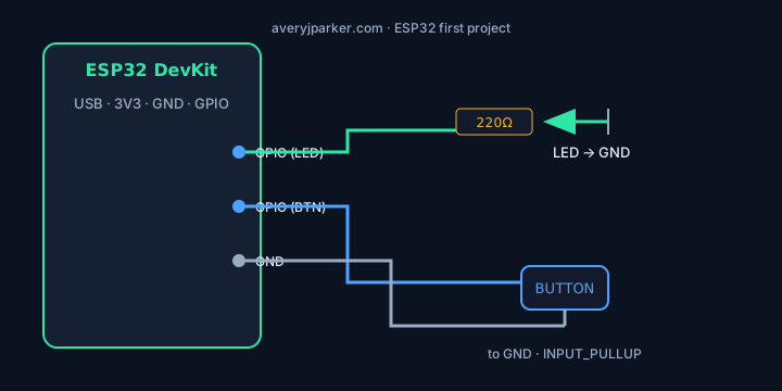
- Option A (easiest): use the onboard BOOT button (often GPIO 0) — no wires
- Option B: external button between GPIO 0 (or any free GPIO) and GND
Use INPUT_PULLUP: idle = HIGH, pressed = LOW. No external pull-up resistor required.
Sketch
// Project 2 — Button + LED feedback
const int BTN = 0;          // BOOT on many DevKits
const int LED = LED_BUILTIN;

void setup() {
  Serial.begin(115200);
  pinMode(BTN, INPUT_PULLUP);
  pinMode(LED, OUTPUT);
  Serial.println("Project 2 — press button (BOOT or wired to GND)");
}

void loop() {
  static bool lastPressed = false;
  bool pressed = digitalRead(BTN) == LOW;

  digitalWrite(LED, pressed ? HIGH : LOW);

  if (pressed != lastPressed) {
    Serial.println(pressed ? "pressed" : "released");
    lastPressed = pressed;
    delay(40); // crude debounce
  }
}
Expected result
- LED follows button state
- Serial prints
pressed/releasedonce per edge (not a flood)
Troubleshooting
- Always pressed: wrong pin; short to GND; try GPIO 4 with external button instead of 0
- Chatter: increase debounce to 50–80 ms; use a cleaner mechanical switch
Done when
One clean edge per physical press/release.
5. Project 3 — External LED + resistor
Goal: Drive an external load correctly (current limiting) — the habit that prevents dead pins.
Wiring
- GPIO 4 → 220 Ω resistor → LED anode (long leg)
- LED cathode (short leg) → GND
Sketch
// Project 3 — External LED on GPIO 4
const int LED = 4;

void setup() {
  Serial.begin(115200);
  pinMode(LED, OUTPUT);
  Serial.println("Project 3 — external LED on GPIO 4");
}

void loop() {
  for (int i = 0; i < 3; i++) {
    digitalWrite(LED, HIGH);
    delay(150);
    digitalWrite(LED, LOW);
    delay(150);
  }
  delay(800);
  Serial.println("blink burst");
}
Expected result
External LED does a triple-blink, pause, repeat. Serial prints blink burst.
Troubleshooting
- Dim/no light: LED backwards; bad breadboard row; resistor too large
- Very bright / hot: missing resistor — unplug immediately
Done when
You can move the LED to another GPIO by changing one constant.
6. Project 4 — Temperature / humidity read
Goal: Read a real sensor on a schedule (basis for automation and logging).
Pick one path below.
Option A — DHT22 (simpler wiring for beginners)
- DHT22 VCC → 3.3 V (some modules want 5 V — check yours)
- DHT22 GND → GND
- DHT22 DATA → GPIO 15
- If module has no onboard pull-up: 4.7k–10k from DATA to 3.3 V
Install library: DHT sensor library by Adafruit (+ Adafruit Unified Sensor).
// Project 4A — DHT22 on GPIO 15
#include <DHT.h>
#define DHTPIN 15
#define DHTTYPE DHT22
DHT dht(DHTPIN, DHTTYPE);

void setup() {
  Serial.begin(115200);
  dht.begin();
  Serial.println("Project 4A — DHT22");
}

void loop() {
  delay(2500); // don't hammer the sensor
  float h = dht.readHumidity();
  float t = dht.readTemperature(); // Celsius
  if (isnan(h) || isnan(t)) {
    Serial.println("Read failed — check wiring / pull-up / power");
    return;
  }
  Serial.print("Temp C: ");
  Serial.print(t, 1);
  Serial.print("  RH %: ");
  Serial.println(h, 1);
}
Option B — BME280 over I²C
- VCC → 3.3 V · GND → GND
- SDA → GPIO 21 · SCL → GPIO 22 (common ESP32 defaults)
Install library: Adafruit BME280 (+ BusIO / Unified Sensor as prompted).
// Project 4B — BME280 I2C
#include <Wire.h>
#include <Adafruit_BME280.h>
Adafruit_BME280 bme;

void setup() {
  Serial.begin(115200);
  if (!bme.begin(0x76) && !bme.begin(0x77)) {
    Serial.println("BME280 not found — run I2C scan / check SDA SCL");
    while (1) delay(10);
  }
  Serial.println("Project 4B — BME280");
}

void loop() {
  Serial.print("T=");
  Serial.print(bme.readTemperature(), 1);
  Serial.print("C  P=");
  Serial.print(bme.readPressure() / 100.0F, 1);
  Serial.print("hPa  H=");
  Serial.print(bme.readHumidity(), 1);
  Serial.println("%");
  delay(3000);
}
Expected result
Stable numbers that change when you breathe on / warm the sensor. Failed reads print a clear error — not silent zeros.
Troubleshooting
- NaN / failed: power, data pin, pull-up, library mismatch (DHT11 vs DHT22)
- BME not found: try address 0x76 and 0x77; confirm 3.3 V not 5 V on some modules
Done when
You have a repeating log line you trust enough to graph later.
7. Project 5 — Relay (low-voltage only while learning)
Goal: Drive a relay module from a GPIO with a simple on/off serial control pattern.
Wiring (module side)
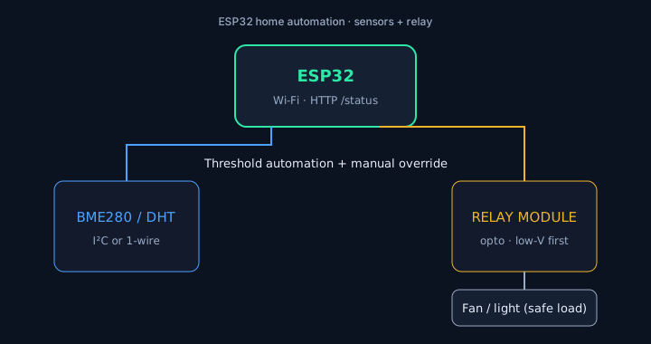
- Relay module VCC → 5 V (if module is 5 V logic) or 3.3 V per module docs
- Relay module GND → ESP32 GND (common ground required)
- Relay module IN → GPIO 5
- Load on the relay COM / NO terminals — low-voltage DC only for this kit (e.g. 5 V fan, LED strip segment with its own supply)
digitalWrite(pin, LOW) = ON.
Confirm with the module LED before connecting anything you care about.
Do not switch mains until you use a proper enclosure, rated relay, and know your local electrical code.
Sketch
// Project 5 — Relay on GPIO 5 (active-low friendly)
const int RELAY = 5;
const bool ACTIVE_LOW = true; // set false if your module is active-high

void relayWrite(bool on) {
  if (ACTIVE_LOW) {
    digitalWrite(RELAY, on ? LOW : HIGH);
  } else {
    digitalWrite(RELAY, on ? HIGH : LOW);
  }
}

void setup() {
  Serial.begin(115200);
  pinMode(RELAY, OUTPUT);
  relayWrite(false);
  Serial.println("Project 5 — relay demo (3s on / 3s off)");
}

void loop() {
  relayWrite(true);
  Serial.println("relay ON");
  delay(3000);
  relayWrite(false);
  Serial.println("relay OFF");
  delay(3000);
}
Combine with Project 4 (mini automation)
// Pseudo-logic you'll use in the full site guide:
// if (temperatureC > 28.0) relayWrite(true);  // e.g. fan
// else if (temperatureC < 26.0) relayWrite(false);
Full write-up: ESP32 home automation with sensors & relays.
Expected result
Relay clicks (or module LED toggles) on a 3 s cadence; serial confirms state.
Troubleshooting
- Board resets when relay fires: power the relay from a separate 5 V supply; common GND
- Logic inverted: flip
ACTIVE_LOW - No click: wrong IN pin; module needs 5 V VCC while ESP is 3.3 V signal — most opto boards still accept 3.3 V IN
Done when
You can turn a safe low-voltage load on/off without the ESP brownout-resetting.
8. Troubleshooting cheat sheet
| Symptom | Likely fix |
|---|---|
| Port missing | Data cable; CP210x/CH340 drivers; another USB port |
| Upload fail / timed out | Hold BOOT; 115200 upload speed; correct board profile |
| Random resets | Weak USB power; motors/relays need separate supply |
| Wi‑Fi later breaks things | Finish offline logic first; then add Wi‑Fi |
| Garbled serial | Wrong baud; multiple monitors open |
| Sensor NaN | Wiring, pull-up, power, library type |
9. What to build next
- Site guide: ESP32 first project (expanded)
- Home automation project
- Pi + ESP32 mesh smart home
- Choose Pi, ESP32, or Arduino
- Upcoming scheduled posts
Books that pair well: AI Workflow Mastery · 3D Printing Mastery · Network Ninja
© 2026 Avery J. Parker · Free for personal learning and classroom use · Please don’t resell this kit as a paid PDF without permission.
Site: averyjparker.com · Print this page for a clean handout (File → Print → Save as PDF).