Project · Beginner · ESP32
Getting Started with ESP32 for Beginners — First Project (Full Bench Guide)
USB data cable → DevKit → breadboard LED + resistor. If the LED never blinks, suspect the cable before the code. This is the long-form companion to the free ESP32 Starter Kit PDF. Goal: a first board that enumer…
Project template
- Goal & materials
- Steps / firmware
- Troubleshooting
- AI assist notes
- Related gear & books
Scope (what this is / is not)
Compared against: Arduino blink demos that skip serial and cable diagnosis. This guide requires expected serial output and a failure table.
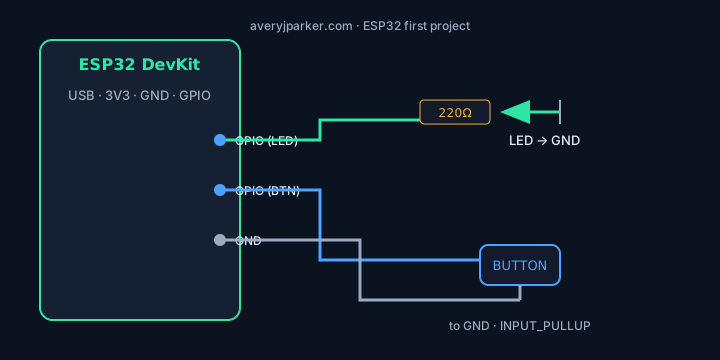
This is the long-form companion to the free ESP32 Starter Kit PDF. Goal: a first board that enumerates, flashes, and blinks on purpose with written expected output.
Skill level & time
- Level: Beginner
- Time: 60–120 minutes including driver drama
- Done when: onboard or external LED toggles at a known period and Serial Monitor prints a heartbeat line every second
BOM (one station)
| Item | Qty | Notes | Ballpark USD |
|---|---|---|---|
| ESP32 DevKit (ESP32-WROOM class) | 1 | USB-C or micro-USB — match your cable | $4–12 |
| USB data cable | 1 | Charge-only cables are the #1 false failure | $3–8 |
| Breadboard | 1 | Half-size fine | $3–6 |
| LED | 1 | Any color | $0.10 |
| Resistor 220–330 Ω | 1 | Series with LED | $0.05 |
| Jumper wires | 3–6 | M-M | $2–5 |
Toolchain (pin versions in your lab notes)
| Tool | Recommendation |
|---|---|
| Arduino IDE | 2.x — fine for lesson one |
| Board package | esp32 by Espressif (install via Boards Manager) |
| Board menu | Match your module (often “ESP32 Dev Module”) |
| Upload speed | 115200 if 921600 fails |
| Next step | PlatformIO once sketches multiply |
Wiring (external LED)
- GPIO 2 → 220–330 Ω → LED anode; LED cathode → GND (confirm your board’s LED polarity / onboard LED GPIO — many DevKits use GPIO2 for onboard LED).
- If using only onboard LED, skip the breadboard and still run the same sketch.
Sketch (complete)
#include <Arduino.h>

// Many ESP32 DevKits map onboard LED to GPIO 2 — change if your silkscreen says otherwise.
static const int LED_PIN = 2;

void setup() {
  pinMode(LED_PIN, OUTPUT);
  Serial.begin(115200);
  delay(500);
  Serial.println("esp32-first: setup complete");
}

void loop() {
  digitalWrite(LED_PIN, HIGH);
  Serial.println("esp32-first: LED on");
  delay(500);
  digitalWrite(LED_PIN, LOW);
  Serial.println("esp32-first: LED off");
  delay(500);
}
Expected output
| Check | Expected |
|---|---|
Device Manager / lsusb / dmesg | USB serial device appears when cable is data-capable |
| Upload | Ends with success; may need BOOT button timing on some clones |
| Serial @ 115200 | Alternating LED on / LED off lines ~1 Hz total cycle |
| LED | Visible blink in phase with serial lines |
Failure table
| Symptom | Likely cause | 10-minute test |
|---|---|---|
| Port missing | Charge-only cable / driver | Try another cable; install CP210x/CH340 driver as needed |
| Upload timeout | Wrong board, bad cable, need BOOT | Hold BOOT, click upload, release on “connecting” |
| Upload OK, no blink | Wrong LED GPIO | Try GPIO 2 and GPIO 5; check schematic for your DevKit |
| Garbled serial | Baud mismatch | Set both sides to 115200 |
| Random resets | Power / flaky USB | Powered hub; shorter cable |
Export it like code
esp32-first/
  README.md          # board revision, cable type, OS
  src/main.cpp       # or .ino
  platformio.ini     # when you graduate
  notes/RESULTS.md   # what worked / failed
Verdict / next project
If the LED and serial agree, you have a working bench — not a finished product. Next: button input, then a sensor from the starter kit PDF. AI can help refactor later; it cannot replace a data cable.